MM 842 LIGHT ACTIVATED SWITCHES
The MM 842 range of light activated switches is specifically designed for the automatic control of anchor and other lights on unattended vessels.
Principal features:
All electronic: there are
no relays or other moving parts to wear out.
Low off-current: daylight battery drain is
negligible.
Low voltage drop: no discernible reduction
of light output.
Flicker protected: high immunity to moving
shadows, lightning and other short term light changes
Interference protected: high immunity to
generator noise, V.H.F. and other transmissions.
Reverse polarity protected: inadvertent reversal
of supply will not cause damage.
Self-checking and signaling in any ambient light:
the lamp illuminates for a short period when power is applied.
Enclosed terminal block: connections are
not exposed to the elements. Integral mounting bracket: facilitates easy
fixing.
Rugged construction: electronics are encapsulated
within a diecast alloy box finished with marine grade polyurethane.
Switch-on and switch-off:
Switch-on and switch-off points are determined by the amount of light reaching the unit, which depends on the mounting position, the relative angle to the sun, the spectral quality of the light and the prevailing visibility. In most circumstances switch-on occurs before sunset; however, exceptional conditions of illumination can delay operation until a little after. Similarly switch-off normally occurs after, but exceptionally before, sunrise.
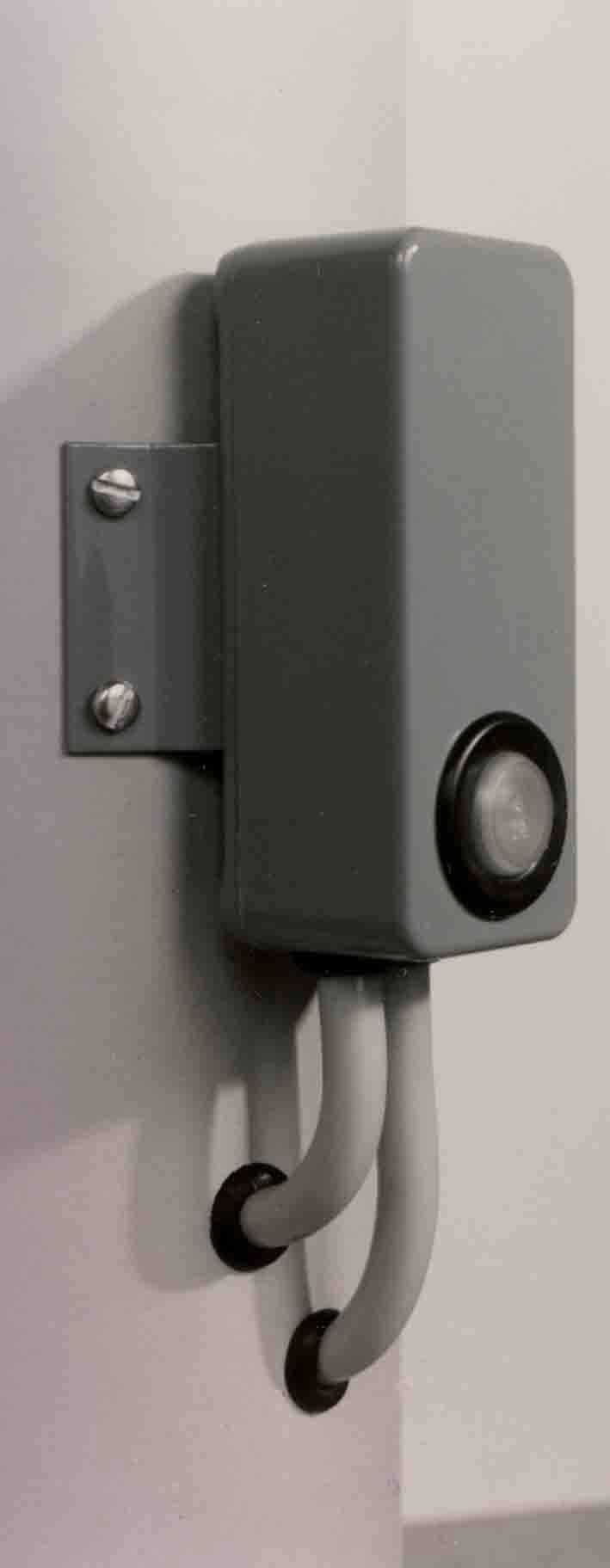
Mounting location:
It is recommended that the unit is mounted near the top of the mast with the cable grommets downwards. However, the unit will operate satisfactorily anywhere it can 'see 'the ambient light. The following positions must be avoided. where it can 'look' at the light it controls; where deck and other lights will shine on it; less than 0. 5m above or below a radar scanner on the same mast; where it will foul running rigging
|
Type
|
Lamp designation
|
Design rating
|
Voltage range
|
|
05W12
|
12V 5W
|
0.45Amps at 12Volts |
8 to 16 Volts
|
|
15W12
|
12V > 10W
|
1.36Amps at 12Volts
|
8 to 16 Volts
|
|
25W12
|
12V 25W
|
2.20Amps at 12Volts
|
8 to 16 Volts
|
|
15W24
|
24 > 10W
|
0.68Amps at 24Volts
|
16 to 32 Volts
|
|
25W24
|
24V 25W
|
1.10Amps at 24Volts
|
16 to 32 Volts
|
Dimensions and weight Unit:
92 x 38 x 27 mm. (3 5/8 x 1 1/2 x 1 1/16 ins.)
Bracket: 70 x 40 mm. (2 3/4 x 1 9/16 ins.)
Weight: 185 g. (6 1/2 oz.)
Electrical characteristics at design rating
Daylight current ... less than 1 mA
On-state current... less than 5%
On-state voltage drop... less than 1%
Daylight initial on-period... more than 5 seconds
Temperature range...- 20 to +50 °C
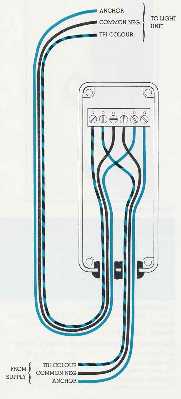
Electrical connections (refer to diagram)
1. If a three-way cable is used to connect a combined tri-colour and anchor light use the DIRECT LINK between the two left-hand terminals to join the tri-colour wire. If wiring is to anchor light only, these terminals are not required.
2. Use the two centre terminals to join the common negative wire; these also provide the negative connection for the unit. IMPORTANT: Always join the negative wire in this manner, joining it externally can cause permanent damage.
3. Connect the anchor light supply wire to the extreme right-hand terminal and the wire leading to the anchor light to the second terminal from the right.
4. Check that each wire is correctly connected and that the terminal screws are firmly but not excessively tightened.
Final assembly:
1. Apply silicone grease (2.5g capsule enclosed) to tops of terminal screws, exposed part of terminal block, to all internal metal surfaces and liberally to the lid flange.
2. If cables do not seal at the grommets or if the unit is to be mounted near to deck level it is recommended that the unit should be filled with silicone rubber compound after application of silicone grease.
3. Fit the lid which should apply additional compression to the cable grommets.
4. If the unit is to be fitted to a curved surface carefully form the mounting bracket to the required profile before final fixing.
Testing:
1. If the wiring to the tri-colour light has been disturbed check the lamp still functions.
2. Switch on the anchor light. If it is already dark it should light and remain on. If it is daylight it should light for a period of more than five seconds then extinguish. During daylight the unit may also be tested by covering the light sensor, taking into account that it will require several seconds to respond